Logic Gates Exam
Logic Gates
Gates are tiny electronic devices that manipulate binary data in fixed ways. Gates are made of a tiny component called a transistor.
The logic gates, together with their truth table, that you need to learn are:
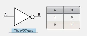
NOT
Where A is the input signal and B is the output.
The output is always the opposite of the input.
AND
Where A and B are the inputs and Q is the output.
The output is 1 if and only if both inputs are 1.

OR
Where A and B are the inputs and Q is the output.
The output is 1 if at least one of the inputs is 1.

NAND
Where A and B are the inputs and Q is the output. NAND is short for NOT AND.
The output is 1 if one of the inputs is 0 (zero).

NOR
Where A and B are the inputs and Q is the output. NOR is short for NOT OR.
The output is 1 if and only if both inputs are 0 (zero).

XOR
Where A and B are the inputs and Q is the output.
The output is 1 if both inputs are different. In other words, if only one of the inputs is 1.

Input Devices
2D scanners
What is a 2D scanner
A 2D scanner is a device that is used for producing an exact digital image replica of a hard-copy document (data on paper) that can be stored on a computer.
Types of scanner
There are different types of scanners: drum scanners, flatbed scanners, hand-held scanners, film scanners.
All scanners work on the same principle of reflectance or transmission.
The most common scanner is the flatbed scanner and this is the one we will study in more detail.
How do 2D scanners work
A scanner consists of a flat transparent glass bed under which the CCD (Charge Couple Device) sensors, lamp, lenses, filters and also mirrors are fixed. The document has to be placed on the glass bed. There will also be a cover to close the scanner.
The lamp brightens up the text to be scanned. Most scanners use a cold cathode fluorescent lamp (CCFL).
(When desktop scanners were first introduced, many manufacturers used fluorescent bulbs as light sources. Then manufacturers moved to cold-cathode bulbs. By late 2000, Xenon bulbs had emerged as an alternative light source. Xenon produces a very stable, full-spectrum light source that’s both long-lasting and quick to initiate. However, xenon light sources do consume power at a higher rate than cold cathode tubes).
A stepper motor under the scanner moves the scanner head from one end to the other. The movement will be slow and is controlled by a belt. The scanner head consists of the mirrors, lens, CCD sensors and also the filter. The scan head moves parallel to the glass bed. The scan head moves from one end of the machine to the other. When it has reached the other end the scanning of the document has been completed.
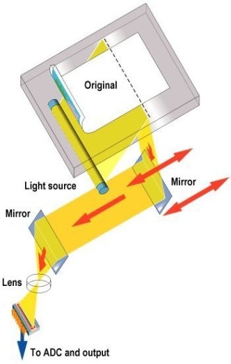
As the scan head moves under the glass bed, the light from the lamp hits the document and is reflected back with the help of mirrors angled to one another.
The amount of light reflected by or transmitted through the image and picked up by the CCD sensors is then converted to a voltage proportional to the light intensity – the brighter the part of the image, the more light is reflected or transmitted, resulting in a higher voltage.
What is a Charge Couple Device (CCD)
What is CCD (from min. 6:25 to 7:35)
A CCD consists of many photo-sensitive elements in a long, thin line; the more photo-sensitive elements per unit length, the higher its resolution.
A CCD is a solid-state electronic device that converts light into an electric charge. The light reflected from the object being scanned is directed into the CCD array via a system of mirrors and lenses. The CCD converts the measured reflectance into an analogue voltage, which is then sampled and changed to digital values by an analogue-to-digital converter (ADC).
Source: http://www.circuitstoday.com/working-of-scanner
https://www.pctechguide.com/scanners/scanner-operation

Application
2D scanners are used at airports to read passports. They make use of OCR (Optical Character Reader) technology to produce digital images which represent the passport pages. Because of the OCR technology, these digital images can be manipulated in a number of ways.
For example, the OCR software is able to review these images, select the text part and then automatically put the text into the correct fields of an existing database.
At many airports, the two-dimensional photograph in the passport is also scanned and stored as a jpeg image. The passenger’s face is also photographed using a digital camera. The two digital images are compared using face recognition software. Key parts of the face are compared, such as the distance between the eyes, width of the nose, shape of the cheekbones, length of the jawline and shape of the eyebrows.
When the image from the passport and the image taken by the camera are compared, these key positions on the face determine whether or not the two images represent the same face.
3D scanner
3D scanners scan solid objects and produce a 3D image. Since solid objects have x, y and z coordinates, these scanners take images at several points along these three coordinates. A digital image which represents the solid object is formed.
Application
The scanned images can be used in Computer-Aided Design (CAD).
They can be sent to 3D printers to produce a working model of the scanned image.
Computed Tomography (CT). CT scanners build up an image of a solid object through a series of very thin slices. Together these 2D slices make up a representation of the 3D solid object. Each slice is built up by the use of X-rays, radio frequencies or gamma imaging; although a number of other methods exist. Each slice is then stored as a digital image in the computer memory. The whole of the solid object is represented digitally in the computer memory.
Depending on how the image is formed, the type of tomographic scanner can have different names: CT (Computed Tomographic) scanner (for X-rays), MRI (Magnetic Resonance Imaging), SPECT (Single Photon Emission Computed Tomography).
Barcode readers
A barcode is a series of dark and light parallel lines of different thickness. The digits from 0 to 9 are each represented by a unique series of lines.
There are various methods to represent these digits. We’ll see the UPC (Universal Product Code) method.
The left-hand and right-hand sides of the barcode are separated using guard bars.
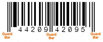
Each digit is represented by two black lines and two white lines of different thickness. The digits on the left have an odd number of black elements and always begin with a white bar; the digits on the right have an even number of black elements and always begin with a black bar. This arrangement allows a barcode to be scanned in any direction.

When a barcode is scanned:
The barcode is first read by a red laser or red LED (Light Emitting Diode).
Light is reflected back off the barcode; the dark areas reflect little or no light which allows the bars to be read.
The reflected light is read by sensors (photoelectric cells).
As the laser or LED light is scanned across the barcode, a pattern is generated which is converted into digital data - this allows the computer to understand the barcode.
For example: the digit 3 on the left generates the pattern W B B B B W B (white and black), this has the binary equivalent of 0111101.
Application
Barcode readers are most commonly found at the checkout in supermarkets.
When the barcode has been read:
The barcode number is looked up in the stock database.
When the barcode number is found, the stock item record is looked up.
The price and other stock item details are set back to the checkout (or Point of Sale Terminal (POS)).
The number of stock items in the record is reduced by one each time the barcode is read.
This new value for number of stock items is written back to the stock item record.
The number of stock items is compared to the re-order level; if it is less than or equal to this value, more stock items are automatically ordered.
Once an order for more stock items is generated, a flag is added to the record to stop re-ordering every time the stock item barcode is read.
When new stock items arrive, the stock levels are updated in the database.
Barcodes are also used in libraries. The barcodes are used in books and on the borrower’s library card. Every time a book is taken out, the borrower is linked to the book automatically. This allows automatic checking of, for example, when the book is due to be returned.
Quick Response (QR) code readers
A QR code consists of a matrix of black squares and dots on a light background which represent certain pieces of information. The data in a QR code can be alphanumeric, numeric, binary or Kanji (a form of Chinese characters that are used in modern Japanese writing system)
A QR code can be read using a smartphone camera. When your smartphone scans this code, it translates that information into something that can be easily understood by humans.
Barcodes can hold up to 30 digits; QR codes can hold over 7000 digits. This obviously gives greater scope for the storage of information.

Application
QR codes can be scanned anywhere using a smartphone. This allows advertising of products on trains, buses, shopping malls and many other places. The code may contain a website link or some form of advertising.
Advantages of QR codes:
There is no need for the user to write down or key in a website address; scanning the QR code does this automatically.
QR codes can store website addresses/URLs that appear in magazines, trains, buses or even on business cards, giving a very effective method of advertising.
Digital cameras
Digital cameras have replaced the traditional cameras that used film to record the photos. Digital cameras simply link to a computer system via a USB port or by using Bluetooth (which enables wireless transfer of photographic files).
These cameras are controlled by a microprocessor which can automatically carry out the following tasks:
adjust the shutter speed
focus the image automatically
operate the flash automatically
adjust the aperture size
adjust the size of the image
remove red eye when the flash has been used
The photograph is captured when light passes through the lens onto a light-sensitive cell. This cell is made up of tiny elements known as pixels. The number of pixels determines the size of the file used to store the photograph. By reducing the resolution to, for example, a jpeg image, the storage requirement is reduced to 4 megabytes. The quality of the photograph also depends on many other factors, such as:
the type of lens used
the lighting
Keyboards
Keyboards are the most common input devices. The keyboard is connected to the computer either by using a USB connection or by wireless connection. In the case of tablets and mobile phones, the keyboard is often virtual or a type of touchscreen technology.
Each character on a keyboard has an ASCII value. Each character pressed is converted into a digital signal, which the computer interprets.
Application

Keyboards are a slow method of data entry and are also prone to errors. But they are probably still the easiest way to enter text into a computer. However, frequent use of these devices can lead to injuries, such as RSI (Repetitive Strain Injury) in the hands and wrists. Ergonomic keyboards can help to overcome this problem, these have the keys arranged differently and are designed to give more support to the wrists and hands when doing a lot of typing.
Mice
How does an optical mouse work?
The mouse is probably still the most common pointing device and comes in various forms:
the more traditional type with a mechanical ball arrangement; connected to the computer through a USB port.
the more modern type that use red LEDs to detect movement in the x-y direction; these are a type of optical mouse.
mice that use either of the above types of technology but use a wireless connection to the computer.
A mouse is fitted with one or two buttons to allow for selection and other functions. Many designs of mouse have a scroll wheel to allow rapid movement up and down the screen.
Trackerballs are seen more often in an industrial environment. A ball on the top of the trackerball is moved to control a cursor on the screen. An advantage is that they don’t need any desk space or special surface.
Most laptop computers have a built-in touchpad. This contains a tactile sensor which allows the user to control a cursor by simply moving a finger over the surface of the pad. Buttons to the left and right of the pad act in the same way as buttons on a mouse.
Touchscreens
They allow a simple touch to launch an application or to carry out many of the functions of pointing devices such as a mouse.
Touchscreen technologies:
Capacitive:
This is made up of many layers of glass that act like a capacitor, creating electric fields between the glass plates in layers. When the top glass layer is touched, the electric current changes and the coordinates where the screen was touched is determined by an on-board microprocessor.
Some benefits are: medium cost technology. Screen visibility is good even in strong sunlight. It permits multi-touch capability. The screen is very durable; it takes a major impact to break the glass.
Drawbacks: allows only the use of bare fingers as the form of input; although the latest screens permit a special stylus to be used.
Resistive
This makes use of an upper layer of polyester (a form of plastic) and a bottom layer of glass. When the top polyester layer is touched, the top layer and the bottom layer complete a circuit. Signals are then sent out which are interpreted by a microprocessor, the calculations determine the coordinates of where the screen was touched.
Some benefits are: it is relatively inexpensive technology. It is possible to use bare fingers, gloved fingers or a stylus to carry out an input operation.
Drawbacks: screen visibility is poor in strong sunlight. It doesn’t permit multi-touch capability. The screen durability is only fair; it is vulnerable to scratches and the screen wears out through time.
Infrared
Infrared touch screen technology do not overlay the display with an additional screen or screen sandwich. Instead, infrared monitors use InfraRed emitters and receivers to create an invisible grid of light beams across the screen. This ensures the best possible image quality. When an object interrupts the invisible infrared light beam, the sensors are able to locate the touch point.
Advantages:
highest image clarity and light transmission of all touch technologies
unlimited touch-life
impervious to surface scratches
Disadvantages:
accidental activation may occur because the infrared beams are actually above the glass surface
Dust, oil, or grease build up on screen or frame could impede light beam causing malfunction
Sensitive to water, snow, rain
May be sensitive to ambient light interference
Higher cost
Interactive whiteboards
An interactive whiteboard is a piece of hardware that looks much like a standard whiteboard but it connects to a computer and a projector in the classroom to make a very powerful tool. When connected, the interactive whiteboard becomes a giant, touch-sensitive version of the computer screen. Instead of using the mouse, you can control your computer through the interactive whiteboard screen just by touching it with a special pen (or, some types of boards, with your finger). Anything that can be accessed from your computer can be accessed and displayed on the interactive whiteboard, for example word documents, PowerPoint presentations, photographs, websites or online materials.
Using special software included with the interactive whiteboard, you can also interact with images and text projected on the board, rearranging them, changing their size, colour, etc. This offers a much more interactive experience than using a standard whiteboard or using a data projector alone.
Microphones
When a microphone picks up sound, a diaphragm vibrates producing an electric signal. This signal goes to a sound card and is converted into digital values and stored in the computer.
If the microphone is being used in a voice recognition system, the user’s voice is detected and then converted into digital. A few words spoken produce a digital wave pattern. Software compares this wave pattern to wave patterns stored in memory to see if they match. If they match, then the person has been correctly identified. Only certain words can be used since the system is designed to recognise only a few key phrases. This technology can be used in security systems.
Speech recognition is a different and more complex technology. This again uses a microphone to input words spoken by a user. But this time the software doesn’t try to recognise the person talking. The spoken words are recognised and shown on a screen, input into a word processor or used in other application.
Both voice recognition and speech recognition can be used in various other applications. For example, voice recognition is used in cars to allow the driver to say commands. Key words have to be used so that the software can compare voice patterns with the limited dictionary of words already stored. These systems are becoming increasingly sophisticated so that normal speech in the car doesn’t trigger an unwanted response by the computer. Newer systems can also be set up to only respond to commands from the driver.

Sensors
Sensors are input devices that read or measure physical properties.
Examples of sensors and their applications:
Temperature sensor. Used to:
Control a central heating system.
Control/monitor a chemical process.
Control/monitor the temperature in a greenhouse.
Moisture (aka humidity) sensor. Used to:
Control/monitor the moisture levels in soil in a greenhouse.
Control/monitor the humidity levels in the air in a greenhouse.
Monitor dampness levels in an industrial application (e.g., monitor moisture in a paint spray booth in a car factory)
Light sensor. Used to:
Switch street lighting on at night and off during the day.
Monitor/control light levels in a greenhouse.
Automatically switch on a car’s headlights when it gets dark.
Infra-red (aka motion) sensor. Used to:
Turn on the windscreen wipers on a car automatically.
Detect intruders in a burglar alarm system.
Count people entering/leaving a building.
Pressure sensor. Used to:
Detect intruders in a burglar alarm system.
Weigh things (e.g. check the weight of a vehicle)
Monitor/control a process where gas pressure is important.
Acoustic (aka sound) sensor. Used to:
Pick up noise levels (e.g. footsteps) in a burglar alarm system.
Detect the noise of liquids dripping in a pipe.
Gas sensor. Used to:
Monitor pollution levels in a river or in the air.
Measure O2 and CO2 levels in a greenhouse.
Check for CO2 leaks in a power station.
pH sensor. Used to:
Monitor/control acidity/alkalinity levels in the soil in a greenhouse.
Monitor environmental pollution in rivers.
Magnetic field sensor. Used in:
any application where detection of changes in a magnetic field is required (e.g. in cell phones, CD players)
anti-lock braking systems in motor vehicles.
Sensors are used in both monitoring and control applications. The difference between these two methods can be seen in the following diagram:

Real-life scenarios where sensors are used:
Monitoring applications
Burglar alarm systems. This type of system carries out the following actions:
The system is activated by keying in a password on a keypad.
The infra-red sensor picks up the movement of an intruder in the building.
The acoustic sensor picks up sounds such as footsteps or breaking glass.
The pressure sensor picks up the weight of an intruder coming through a door or through a window.
The sensor data is passed through an ADC (Analogue to Digital Converter) if it is in an analogue form to produce digital data.
The computer will sample the digital data coming from these sensors at a given frequency (e.g. every 5 seconds); the data is compared with the pre-set values (stored values).
If any of the incoming data values are outside the acceptable range, then the computer sends a signal to:
a siren to sound the alarm, or
a light to start flashing.
A DAC (Digital to Analogue Converter) is used if the devices need analogue values to operate them.
The alarm continues to sound, the lights continue to flash until the system is reset with a password.
Monitoring of patients in a hospital.
A number of sensors are attached to the patient; these measure vital signs such as: temperature, heart rate, breathing rate, etc.
These sensors are all attached to a computer system.
The computer samples the data at frequent intervals.
The range of acceptable values for each parameter is keyed in to the computer.
The computer compares the values from the sensors with those values keyed in.
If anything is out of the acceptable range, a signal is sent by the computer to sound an alarm.
If data from the sensors is within range, the values are shown in either graphical form on a screen and/or a digital read out.
Monitoring continues until the sensors are disconnected from the patient.
Measuring pollution in a river.
The sensors are placed in at least two different positions so that a pollution comparison can be made.
The data from the sensors is converted into digital using an ADC and sent to a computer.
The computer stores the received data.
The oxygen levels and acidity levels are compared to the historical data stored in memory and they are also compared to pre-set levels stored in memory.
The oxygen and acidity levels from the different positions in the river are also compared to see if they are similar - this is used to see if the source of the pollution can be found.
One of two things will now happen: either the data is transferred to a DVD or to a memory stick and taken away for further analysis or the computer is connected to a mobile phone network and transmits the data back automatically to the monitoring station.
Other sensors, such as light sensors, to see if there are solids or chemicals in the water blocking out light, can also be used.
Control applications
Control of street lighting. A microprocessor is used to control the operation of a street lamp. The lamp is fitted with a light sensor which constantly sends data to the microprocessor. The data value from the sensor changes according to whether it is sunny, cloudy, raining or it is night time, etc.
The light sensor sends data to the ADC interface.
This digitises the data and sends it to the microprocessor.
The microprocessor samples the data let’s say every minute.
If the data value from the sensor is smaller than the value stored in memory:
a signal is sent from the microprocessor to the street lamp
and the lamp is switched on.
The lamp stays switched on for 30 minutes before the sensor readings are sampled again (this prevents the lamp flickering off and on during brief heavy cloud cover, for example)
If the data from the sensor is greater or equal than the value stored in memory:
a signal is sent from the microprocessor to the street lamp
and the lamp is switched off.
The lamp stays switched off for 30 minutes before sensor readings are sampled again.
Anti-lock braking systems (on cars). ABS use magnetic field sensors to stop the wheels locking up on the car if the brakes have been applied too sharply.
When one of the car wheels rotates too slowly (i.e. it is locking up), a magnetic field sensor sends data to a microprocessor.
The microprocessor checks the rotation speed of the other three wheels.
If they are different (i.e. rotating faster), the microprocessor sends a signal to the braking system:
and the braking pressure to the affected wheel is reduced
the wheel’s rotational speed is then increased to match the other wheels.
Checking the rotational speed using these magnetic field sensors is done several times a second and the braking pressure to all the wheels can be constantly changing to prevent any of the wheels locking up under heavy braking.
If one of the wheels is rotating too quickly, braking pressure is increased to that wheel until it matches the other three.
Automatic oven/cooker. An automatic cooker/oven has temperature sensors and a number of controls to set the cooking time. First of all, the start time and end time (or the actual cooking time) are entered. Finally, the cooking temperature is selected.
The microprocessor checks the set time against the current time and when they are equal, the cooker/oven heating elements are switched on. Once the cooker/oven starts the cooking process, the microprocessor then constantly checks the end time against current time (the end-time may be a pre-set value entered by the user or it may be a value calculated by the microprocessor, based on the cooking time entered); when they are equal, the cooking process is stopped.
The microprocessor checks the temperature data sent from a sensor and turns the heating element on if the value is less than the pre-set value chosen by the user. If the temperature is greater than or equal to the pre-set value, then the heating element is switched off by the microprocessor.
Once the cooking process is finished, the microprocessor sends a signal to a beeper to make a beeping sound to indicate that the cooking cycle is completed.
Central heating systems. In this heating system a gas supply is used to heat water in a boiler. A valve on the gas supply is controlled by a microprocessor and is opened if the heating levels need to be increased. A water pump is used to pump hot water around the central heating system whenever the temperature drops below a pre-set value.
So how does this work?
The required temperature is keyed in and this is stored in the microprocessor memory (this is the pre-set value).
The temperature sensor constantly sends data readings to the microprocessor.
The sensor data is first sent to an ADC to convert the analogue data into digital data.
The digital data is sent to the microprocessor.
The microprocessor compares this data with the pre-set value.
If the temperature reading is greater than or equal to the pre-set value then no action is taken.
If the temperature reading is less than the pre-set value, then a signal is sent:
to an actuator (via a DAC) to open the gas valve to the boiler.
to an actuator (via a DAC) to turn on the water pump.
The process continues until the central heating is switched off.
Chemical process control. A certain chemical process only works if the temperature is above 70ºC and the pH (acidity) level is less than 3.5. Sensors are used as part of the control system. A heater is used to heat the reactor and valves are used to add acid when necessary to maintain the acidity. How the sensors and computer are used to control this process is described below:
temperature and pH sensors read data from the chemical process.
this data is converted to digital using an ADC and is then sent to the computer.
the computer compares the incoming data with pre-set values stored in memory if the:
temperature is less than 70ºC, a signal is sent to switch on the heaters.
temperature is greater than or equal to 70ºC, a signal is sent to switch off the heaters.
pH is greater than 3.5, then a signal is sent to open a valve and acid is added.
pH is less than or equal to 3.5, then a signal is sent to close this valve.
the computer signals will be changed into analogue signals using a DAC so that it can control the heaters and valves.
this continues as long as the computer system is activated.
Output Devices
Inkjet printers
Inkjet printers are made up of:
a print head which consists of nozzles which spray droplets of ink on to the paper to form characters
an ink cartridge or cartridges; either a group of cartridges for each colour (blue, yellow and magenta) and a black cartridge or one single containing all three colours plus black (some systems use six colours).
a stepper motor and belt which moves the print head assembly across the page from side to side.
a paper feed which automatically feeds the printer with pages as they are required.
The ink droplets are produced using two different technologies:
Thermal bubble: tiny resistors create localised heat which makes the ink vaporise. This causes the ink to form a tiny bubble; as the bubble expands, some of the ink is ejected from the print head onto the paper. When the bubble collapses, a small vacuum is created which allows fresh ink to be drawn into the print head. This continues until the printing cycle is completed.
Piezoelectric: a crystal is located at the back of the ink reservoir for each nozzle. The crystal is given a tiny electric charge which makes it vibrate. This vibration forces ink to be ejected onto the paper; at the same time more ink is drawn in for further printing.
When a user wishes to print a document using an inkjet pinter, the following sequence of events takes place. Whatever technology is used, the basic steps in the printing process are the same.
The data from the document is sent to a printer driver (the software of the printer).
The printer driver ensures that the data is in a format that the chosen printer can understand.
A check is made by the printer driver to ensure that the chosen printer is available to print (e.g. checks if the printer is busy, off, out of ink, etc.)
The data is then sent to the printer and it is stored in a temporary memory known as a printer buffer.
A sheet of paper is then fed into the main body of the printer; a sensor detects whether paper is available in the paper feed tray - if it is out of paper (or paper is jammed) then an error message is sent back to the computer.
As the sheet of paper is fed through the printer, the print head moves from side to side across the paper printing the text or image; the four ink colours are sprayed in their exact amounts to produce the desired final colour.
At the end of each full pass of the print head, the paper is advanced very slightly to allow the next line to be printed; this continues until the whole page has been printed.
If there is more data in the printer buffer, then the whole process from stage 5 is repeated until the buffer is finally empty.
Once the printer buffer is empty, the printer sends an interrupt to the processor in the computer; this is a request for more data to be sent to the printer; the whole process continues until the whole of the document has been printed.
Laser printers
They use dry powder ink rather than liquid ink and make use of the properties of static electricity to produce the text and images. Unlike printers, laser printers print the whole page in one go (inkjet printers print the page line by line).
Their advantage is the speed at which they can carry out large print jobs and the fact that they don’t run out of ink halfway through.
The following stages describe how a document is printed using a laser printer:
The data from the document is sent to a printer driver.
The printer driver ensures that the data is in a format that the chosen printer can understand.
A check is made by the printer driver to ensure that the chosen printer is available to print (e.g. checks if the printer is busy, off, out of ink, etc.)
The data is then sent to the printer and it is stored in a temporary memory known as a printer buffer.
The start of the printing process involves a printing drum being given a positive charge; as this drum rotates, laser beam is scanned across it removing the positive charge in certain areas; this leaves negatively charged areas which exactly match the text/images of the page to be printed.
The drum is then coated with positively charged toner (powdered ink); since the toner is positively charged, it only sticks to the negatively charged parts of the drum.
A negatively charged sheet of paper is then rolled over the drum.
The toner on the drum now sticks to the paper to produce an exact copy of the page sent to the printer.
To prevent the paper sticking to the drum, the electric charge on the paper is removed after one rotation of the drum.
The paper finally goes through a fuser which is a set of heated rollers; the heat melts the ink so that it fixes permanently to the paper.
At the very end, a discharge lamp removes all the electric charge from the drum making it ready to print the next page.
Applications of inkjet and laser printers
Inkjet printers are best for one-off photos or where only a few pages of good quality, colour printing are needed; the small ink cartridges or small paper trays would not be an issue with such applications.
Laser printers produce high quality printouts and are very fast when making multiple copies of a document; any application that needs high-volume printing would choose the laser printer (for example, producing a large number of high quality flyers or posters for advertising) - they have two advantages: they have large toner cartridges and large paper trays.
3D printers
3D printers are used in Computer-Aided Design (CAD) applications. They can produce solid objects which actually work. The solid object is built up layer by layer using materials such as powdered resin, powdered metal, paper or ceramic powder.
How 3D printers operate:
A design is made using computer-aided design (CAD) software (for example, Sketchup).
The finalised drawing is imported into some special software that prepares it in a format which is understood by the 3D printer.
The 3D printer is set up to allow the solid object to be made.
The solid object is built up layer by layer (often only 0.1 mm thick); this can take several hours, depending on the thickness of the layers, the material used and the size of the final object.
The object is removed from the printer and is then prepared; for example, some use a jelly-like support which needs to be washed away by immersion in water, some require the removal of excess plastic powder and others require the cutting away of unused material; in many cases, the object has to be left to cure for a few hours.
Uses of 3D printing:
Prosthetic limbs made to exactly fit the recipient.
Items to allow precision reconstructive surgery (e.g. facial reconstruction following an accident); the parts made by this technique are more precise in their design since they are made from exact scanning of the skull.
In aerospace, manufacturers are looking at making wings and other parts using 3D technology; the bonus will be lightweight precision parts.
In fashion and art - 3D printing allows new creative ideas to be developed.
Making parts for items no longer in production, e.g. suspension parts for a vintage car.
2D and 3D cutters
A three-dimensional laser cutter works in a similar way to a two-dimensional cutter. The main difference is that the 3D cutter can recognise an object in the x-y-z direction rather than just x-y.
3D laser cutters can cut the following materials:
glass
crystal
metal
polymer
wood
Very complex designs can be cut since the cutters are controlled by computers and very sophisticated software.
A 3D cutter can cut beyond the surface of the material and produce very intricate designs.
It is interesting to contrast this method of shaping objects with 3D printers, although it is true to say that not all the materials which can undergo 3D cutting can be used in 3D printing methods.
Actuators
An actuator is an electromechanical device such as a valve and motor. These require a Digital to Analogue Converter (DAC) so that they receive an electric current rather than a simple digital signal direct from the computer.
Speakers and headphones
Sound is produced from a computer by passing the digital data through a Digital to Analogue Converter (DAC) and then through an amplifier; finally the sound emerges from a speaker.
The sound is produced by voltage differences vibrating a cone in the speaker housing at different frequencies and amplitudes.
Liquid Crystal Display (LCD) and Light-Emitting Diode (LED) monitors
The front layer of the LCD monitor is made up of liquid crystal diodes; these tiny diodes are grouped together in threes or fours which are known as pixels (picture elements). The three colours which are grouped together use red, green and blue diodes. Those systems that use groups of four include a yellow diode.
Modern LCD monitors are back lit using Light Emitting Diode (LED) technology. This gives the image better contrast and brightness. Before the use of LEDs, LCD monitors used a cold cathode fluorescent lamp (CCFL) as the backlighting method.
Essentially, CCFL uses two fluorescent tubes behind the LCD screen which supplies the light source. When LEDs are used, a matrix of tiny LEDs is used behind the LCD screen. Because LCD doesn’t emit any light, some form of back-lit technology needs to be used.
LEDs have become increasingly popular because:
LEDs reach their maximum brightness almost immediately (there is no need to warm up before reaching full efficiency)
LEDs give a whiter light which sharpens the image and make the colours appear more vivid; CCFL had a slightly yellowish tint.
LEDs produce a brigghter light which improves the colour definition.
Monitors using LED technology are much thinner than monitors using CCFL technology.
LEDs last almost indefinitely; this makes the technology more reliable and means a more consistent product.
LEDs consume very little power which means they produce less heat as well as using less energy.
Digital Light Projectors (DLP)
These type of projectors use millions of micro mirrors on a small DLP chip.
The number of micro mirrors and the way they are arranged on the DLP chip determines the resolution of the digital image.
When the micro mirrors tilt towards the light source, they are ON. When the micro mirrors tilt away from the light source, they are OFF. This creates a light or dark pixel on the projection screen. The micro mirrors can switch on or off several thousand times a second creating various grey shades - typically 1024 grey shades can be produced (for example, if the mirror switches on more often than it switches off, it will produce a lighter shade of grey). This is known as the grey scale image.
A bright white light source (e.g. from a xenon bulb) passes through a colour filter on its way to the DLP chip. The white light is split into the primary colours: red, green and blue - the DLP projector can create over 16 million different colours. The ON and OFF states of each micro mirror are linked with colours from the filter to produce the coloured image.
The whole concept is a little like reverse black and white photography. With DLP technology, the grey scales are interpreted as colours rather than grey representing colours as used in photography.
LCD projectors
These are older technology than DLP. Essentially a high-intensity beam of light passes through an LCD display and then onto a screen. This works like this:
A powerful beam of white light is generated from a bulb or LED inside the projector body.
This beam of light is then sent to a group of chromatic-coated mirrors; these reflect the light back at different wavelengths.
When the white light hits these mirrors, the reflected light has wavelengths corresponding to red, green and blue light components.
These three different coloured light components pass through three LCD screens; these screens show the image to be projected as millions of pixels in a grey scale.
When the coloured light passes through the LCD screens, a red, green and blue version of the grey image emerges.
These images are then combined using a special prism to produce a full colour image - this final image consists of millions of colours.
Finally the image passes through the projector lens onto a screen.
Memory, storage devices and media
Memory and storage devices can be split up into 3 groups:
Primary memory: RAM and ROM.
Secondary storage: hard disk drive (HDD) and solid state drive (SSD)
Off-line storage: digital versatile disk (DVD), compact disc (CD), Blu-ray disc, USB flash memory and removable HDD.
Primary memory
Random Access Memory (RAM):
It is volatile, it means the contents of the memory are lost when he power to the RAM is turned off.
It is used to store: data, files, or part of the operating system that are currently in use.
It can be written to or read from and the contents of the memory can be changed.
Read Only Memory (ROM):
They are non-volatile, the contents of the memory remain even when the power to the ROM is turned off.
They are often used to store the start-up instructions when the computer is first switched on (for example, ROM might store the basic input/output system (BIOS)).
The data or contents of a ROM chip can only be read; they cannot be changed.
Secondary storage
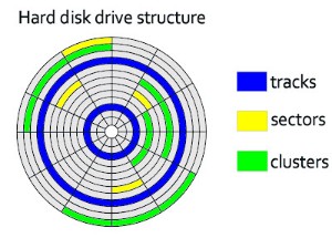
Hard Disk Drives (HDD). These are magnetic media. Data is stored in a digital format on the magnetic surfaces of the disks (or platters, as they are frequently called). The hard disk drive will have a number of platters which can spin at about 7000 times a second. A number of read-write heads can access all of the surfaces in the disk drive. Normally each platter will have two surfaces which can be used to store the data. These read-write heads can move very quickly - typically they can move from the centre of the disk to the edge of the disk (and back again) 50 times a second.
Data is stored on the surface in sectors and tracks. A sector on a given track will contain a fixed number of bytes.
Unfortunately, hard disk drives have very slow data access when compared to, for example, RAM. Many applications require the read-write heads to constantly seek for the correct blocks of data; this means a large number of head movements. The effects of latency then become very significant. Latency is defined as the time it takes for a specific block of data on a track to rotate around to the read-write head.
Users will sometimes notice the effect of latency when they see messages such as “not responding”.
Solid State Drives (SSD). SSDs remove the issue of latency considerably. They have no moving parts and all data is retrieved at the same rate. They don’t rely on magnetic properties; the most common type of solid-state storage devices store data by controlling the movement of electrons within NAND chips. The data is stored as 0s and 1s in millions of tiny transistors within the chip. This effectively produces a non-volatile rewritable memory.
Off-line storage

CD/DVD disks. These are optical storage media. Laser light is used to read data and to write data in the surface of the disk.
Both CDs and DVDs use a thin layer of metal alloy or light-sensitive organic dye to store the data and a spiral track which runs from the centre of the disk to the edge.
The data is stored in ‘pits’ and ‘bumps’ on the spiral track. A red laser is used to read and write the data. CDs and DVDs can be designated R (write once only) or RW (can be written to or read from many times).
DVD technology is slightly different to CDs. One of the main differences is the use of dual-layering which considerably increases the storage capacity. Basically, this means that there are two individual recording layers. Two layers of a standard DVD are joined together with a transparent spacer, and a very thin reflector is also sandwiched between the two layers. Reading and writing of the second layer is done by a red laser focusing at a fraction of a millimetre difference compared to the first layer.
Single layer DVDs still have a larger storage capacity than CDs because the pit size and track width are both smaller. This means that more data can be stored on the DVD surface.
DVD-RAM. Features:
Instead of a single, spiral track, they use a number of concentric tracks
Use of concentric tracks allows simultaneous read and write operations to take place.
They allow numerous read and write operations and have great longevity (over 30 years) which makes them ideal for archiving.

Blu-ray disks. These are another example of optical storage media. Characteristics:
A blue laser is used to carry out read and write operations.
Using blue laser light means that the pits and bumps can be much smaller; consequently, blu-ray can store up to five times more data than normal DVD.
Blu-ray uses a single 1.1 mm thick polycarbonate disk; normal DVDs use a sandwich of two 0.6 mm thick disks.
Using two sandwiched layers can cause errors; because Blu-ray uses only one layer, the disks don’t suffer reading errors.
Blue-ray disks automatically come with a secure encryption system which helps to prevent piracy and copyright infringement.
USB flash memories. These use solid-state technology. They usually connect to a computer through the USB port. Their main advantage is that they are very small, lightweight devices which make them suitable as a method for transferring files between computers. They can also be used as small back-up devices for music or photo files.
Complex or expensive software, such as expert systems, often use memory sticks as a dongle. The dongle contains additional files which are needed to run the software. Without this dongle, the software won’t work properly. It therefore prevents illegal or unauthorised use of the software, and also prevents copying of the software since, without the dongle, it is useless.
Digital cameras use a slightly different form of solid-state memory, known as eXtreme Digital (XD) or secure digital (SD). The technology is essentially the same as memory sticks. These memory cards allow photos to be transferred from camera to computer via the USB port. Many printers and computers also have card slots allowing the device to read the memory card directly.
Removable HDD. These are essentially HDD but can be connected to the computer using one of the USB ports. In this way, they can be used as a back-up device or as another way of transferring files between computers.
Operating systems
The operating system (OS) is software running in the background of a computer system. It manages many of the following basic functions:
User interfaces, it is the way in which the computer user communicates with the computer.
Multitasking, allows multiple applications to run at the same time.
Loading and running of applications (software)
File utilities (e.g. copy, save, sort, delete).
Manages user accounts.
Security (manages log on, passwords), provides security through user accounts and passwords.
Processor management, executes and cancels processes and divides processing time.
Memory management, transfers programs into and out of memory, allocates free space between programs, and keeps track of memory usage.
Manages interrupts.
Manages the hardware.
Without the OS, the majority of users would find it almost impossible to work with computers on a day-to-day basis.
When a computer is first powered up, the initiating programs are loaded into memory from the ROM chip. These programs run a checking procedure to make sure the hardware, processor, internal memory and bios (basic input-output system) are all functioning correctly. If no errors are detected, then the operating system is loaded into memory.
Interrupts
An interrupt is a signal sent from a device or from software to the processor. This will cause the processor to temporarily stop what it is doing and service the interrupt. Interrupts can occur when, for example:
a disk drive is ready to receive more data
an error has occurred, such as a paper jam in a printer
the user has pressed a key to interrupt the current process, for example, CTRL-ALT-DEL
a software error has occurred - for example, if an exe file couldn’t be found to initiate the execution of a program
Once the interrupt signal is received, the processor either carries on with what it was doing or stops to service the device or program that generated the interrupt.
Interrupts allow computers to carry out many tasks or to have several windows open at the same time. Whenever an interrupt is serviced, the status of the current task being run is saved. This is done using an Interrupt Handler and once the interrupt has been fully serviced, the status of the interrupted task is reinstated and it continues from the point prior to the interrupt being sent.
The following flowchart shows how buffers and interrupts are used when a document is sent to a printer.

High and low-level languages and their translators
Computer programs can be written in high-level languages or low-level languages, depending on the task to be performed and the computer to be used.
High-level languages
They enable a programmer to focus on the problem to be solved and require no knowledge of the hardware and instruction set of the computer that will use the program.
High-level languages are designed with programmers in mind; programming statements are easier to understand than those written in a low-level language. This means that programs written in a high-level language are easier to:
read and understand as the language used is closer to human language
write in a shorter time
debug at the development stage
maintain once in use
The following code is written in a high-level language program:
result := num1 + num2;
These are examples of high-level programming languages: C++, Pascal, Python, Visual Basic, JavaScript.
Low-level languages
Low-level languages relate to the specific architecture and hardware of a particular type of computer. Low-level languages can refer to machine code, the binary instructions that a computer understands, or an assembly language that needs to be translated into machine code.
Assembly languages
Few programmers write programs in an assembly language. Those programmers who do, do so for the following reasons:
to make use of special hardware
to make use of special machine-dependent instructions
to write code that doesn’t take up much space in primary memory
to write code that performs a task very quickly
The following program that adds two numbers is written in a typical assembly language:
LDA First
ADD Second
STO Sum
In order to understand this program the programmer needs to know that:
LDA means load the value of the variable into the accumulator.
ADD means add the value of another variable to the value stored in the accumulator
STO means to replace the value of the variable by the value stored in the accumulator.
Machine code
Programmers do not usually write in machine code as it is difficult to understand and it can be complicated to manage data manipulation and storage.
The following program adds two numbers and is written in typical machine code:
0001 00010010
0100 00010011
0000 00011010
Translators
Programs need to be translated into machine code so the computer can “understand” them; this is done by a program called a translator. There are several types of translator programs in use; each one performs a different task.
Compilers. It is a computer program that translates a program written in a high-level language into machine code so that it can be directly used by a computer to perform a required task. Once a program is compiled the compiler generates an executable file which can be used again and again to perform the same task without recompilation.
Interpreters. It is a computer program that reads a statement (line of code) from a program written in a high-level language, performs the action specified (translate to machine code) and if it finds an error the interpreter stops the translation. If no error was found, the interpreter does the same with the next statement and so on. It doesn’t create any additional file.
Assemblers. It is a computer program that translates a program written in an assembly language into machine code so that it can be directly used by a computer to perform a required task. Once a program is assembled the machine code can be used again and again to perform the same task without re-assembly.
Computer architecture and the fetch-execute cycle
Early computer programs were hard-wired. To reprogram a computer meant changing the hardware switches manually, that took a long time with potential errors.
Computer memory was only used for storing data.
The principle of the Von Neumann architecture is that data and programs are stored in the same memory.
Programs are fetched from memory for execution by the CPU.
Programs and data are represented in memory in the same way.
The instructions in memory are fetched one at a time.
Charateristics of the Von Neumann architecture
It has a Central Processing Unit (CPU). The purpose of the CPU is to fetch, decode and execute instructions.
The CPU consists of the following components:
- Control Unit (CU): sends signals to control how data moves around the CPU.
- Arithmetic Logic Unit (ALU), performs calculations and logical decisions.
- Cahe, provides fast access to frequently used instructions and data.
- Registers:
Program Counter (PC): holds the address of the next instruction in memory.
Memory Address Register (MAR): holds the address of where data is to be fetched or stored.
Memory Data Register (MDR): holds the data fetched from, or to be written to the memory.
Accumulator (ACC): holds the results of calculations.
A Von Neumann architecture follows this pattern:
Fetch
An instruction and the necessary data are obtained from memory.
Decode
The instruction and data are separated, and the components and pathways required to execute the instruction are activated.
Execute
The instruction is performed, the data is manipulated, and the results are stored.
Computers are complex machines capable of fetching and executing instructions billions of times a second
Example:
Each instruction is stored in a location in memory. Each location in memory has an address.

The following is a simple representation of the John von Neumann model which shows how a processor and memory unit are linked together by connections known as buses.
Buses
Buses are the wires that connect the processor to the memory unit and the input and output devices. They move data around the computer and also send out control signals to make sure everything is properly synchronised.

Address bus. The sole function of the address bus is to carry an address. This address is loaded on to the bus from the MAR (when the control unit orders it). It is unidirectional, signals travel in one direction only. It sends an address to memory, it cannot be used to carry an address from the memory back to the CPU.
Data bus. Sends data between the processor, the memory unit and the input/output devices. The data might be an instruction, an address or a value. It is bi-directional, data can travel in both directions.
Control bus. Carries signals relating to the control and coordination of all activities within the computer, for example, read and write signals. It is bi-directional, signals travel in both directions.
Addresses and Registers

An address is the location of where the data can be found in a computer memory. Each address in memory is unique. In the diagram above the addresses are contained in the memory unit.
A register is simply a high-speed storage area within the computer. All data is stored in a register before it can be processed. For example, if two numbers are to be added, both numbers must be stored in registers and the result of the addition must also be stored in a register.
The abbreviations of the register shown in the figure above stand for:
MAR: memory address register
MDR: memory data register
ALU: arithmetic and logic unit
PC: program counter
CIR: current instruction register
Memory unit
The computer memory unit is made up of a number of partitions. Each partition consists of an address and its contents. The example shown here uses 8 bits for each address and 8 bits for the content. In a real computer memory, the address and its contents are actually much larger than this.

The address will uniquely identify every location in the memory and the contents will be the binary.
Processor
The processor contains the arithmetic and logic unit (ALU) and the Control Unit. The ALU allows arithmetic and logic operations to be carried out.
The control unit controls the operation of the memory, processor and input/output devices. It contains the current instruction register (CIR) and the program counter (PC). The CIR contains the current instruction during processing. The PC contains the address of the next instruction to be executed.
Essentially, the control unit reads an instruction from memory (the address of the location where the instruction can be found is stored in the Program Counter (PC). This instruction is then interpreted. During that process, signals are generated along the control bus to tell the other components in the computer what to do.
The fetch-execute cycle
To carry out a set of instructions, the processor first of all fetches some data and instructions from memory and stores them in suitable registers. Both the address bus and the data bus are used in this process. Once this is done, each instruction needs to be decoded before finally being executed. This is all known as the fetch-execute cycle.
Fetch. In the fetch-execute cycle, the next instruction is fetched from the memory address currently stored in the Program Counter (PC) and is then stored in the Current Instruction Register (CIR). The PC is then incremented (increased by 1) so that the next instruction can be processed. This is then decoded so that each instruction can be interpreted in the next part of the cycle.
Execute. The processor passes the decoded instruction as a set of control signals to the appropriate components within the computer system. This allows each instruction to be carried out in its logical sequence.
